DIY MIDI-based monitor controller setup
09 Sep 2017 by Nod Steady
In my home studio, I have three sets of monitors (speakers), plus headphones. So I needed a controller to easily switch between them. However, I use Sonarworks to calibrate the sound of my main monitors (and my headphones). So a regular monitor controller that routes the audio signal (from one input) to the chosen speakers would not work well: I would then have to switch on and off calibration (as well as changing calibration profiles) when switching between different speakers and the headset.
Before Sonarworks released their system wide plugin, they used to have a blog post explaining how one could use Soundflower and a VST host to get system wide calibration. I took that idea a bit further: As I have a Roland Octa Capture audio card with multiple outputs, I wanted to use a VST host to route the signals to the various outputs. I could then connect each speaker set and the headphone amp to each output. Then, I could use the mute/unmute buttons in the VST host to control the monitors. And given that the VST host could be controlled via MIDI, I could use physical buttons to control the outputs.
I chose LiveProfessor as my VST host, and it worked great! Soundflower turned out to be a bit buggy as well as having too much delay when I routed audio from my inputs to my outputs. So I replaced it with Loopback, which seems to work nicely. There is still some latency though, and for now I bypass the whole setup when recording e.g. vocals. Luckily, recording and mixing are usually happening at different times, so it’s no big issue.
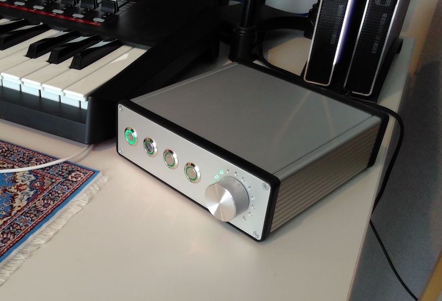
At first, I assigned some buttons on my MIDI keyboard to control the monitors. But those buttons were already assigned in my DAW of choice (Propellerhead Reason), which led to some random and unpredictable behavior. Also, I wanted a large physical system-wide volume control with feedback. So I started designing my own MIDI box.
Doing some research, I figured that using an Arduino would fit my project well. There are other projects out there that is made specifically for DIY MIDI, but for various reasons I didn’t find any of them to fit this project (as well as some future projects I have planned; more on that another time).
It was easy to set up a prototype on a breadboard, and working as programmer, the programming part was pretty straight forward. The NeoPixel LED ring caused some headache, as it interfered with the MIDI data. It also took some time to work out the infinite (double) potentiometer. However, the hardest part was figuring out how to do the physical stuff: What parts were I to use? Would I need a circuit board?
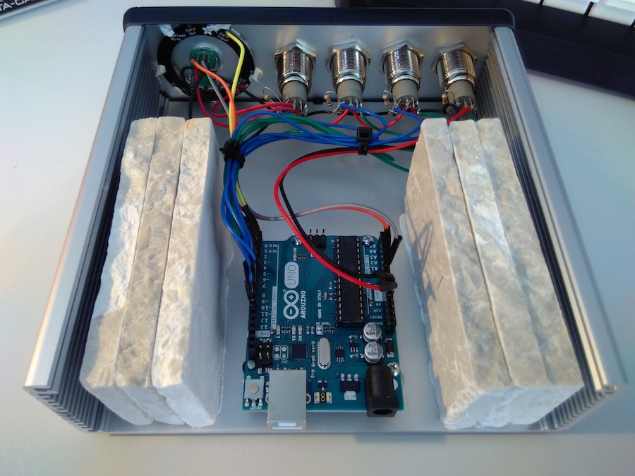
After a lot of research, I ended up using these parts:
- Arduino Uno
- Four metal pushbuttons
- NeoPixel LED ring
- Double “infinite” potentiometer
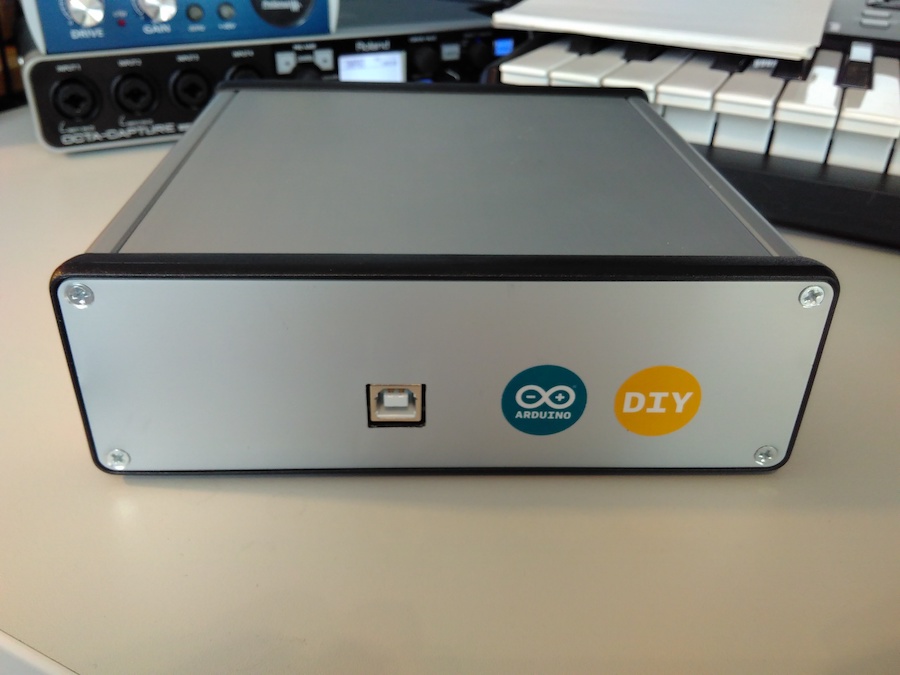
- Box from Hammond Manufacturing (the 160x165x52mm one)
- Knob from Mentor
- Four resistors (for the button leds).
I got help making the holes in the front panel of the box that I had purchased. The small holes were easy (just remember that aluminium melts when it gets hot, so use low speed and perhaps some oil when drilling), but I didn’t have what I needed for the 16mm button holes. I skipped using a circuit board, as it would just add clutter and extra wires.
Then, I flashed the Arduino using HIDUINO to become an actual MIDI USB device, so that I wouldn’t need serial-to-MIDI conversion of the USB communication.
Lastly, I glued some stones inside the box. This gives it some weight so that it doesn’t move when pushing the buttons.